A 5-year-old girl was referred to our pediatric unit for her arrhythmic issue.
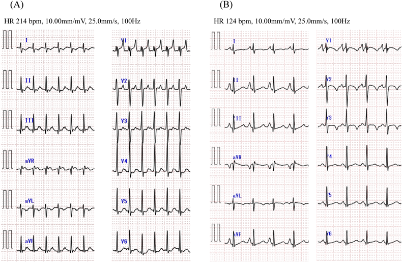
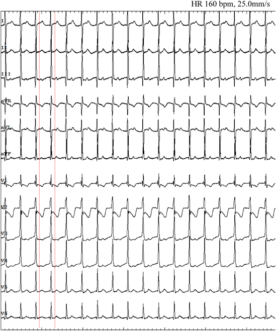
At the age of 3, she presented malaise and peripheral edema seen at a local hospital. Electrocardiogram (ECG) showed a short RP narrow QRS complex tachycardia of 200–220 beats per minute (bpm) (Fig. 1A). Supraventricular tachycardia (SVT) was once suppressed by intravenous adenosine triphosphate, but it reappeared and alternately persisted and ceased every few hours. Echocardiography at the time of SVT cessation revealed normal cardiac anatomy with abnormal left ventricular function (left ventricular ejection fraction [LVEF] 48%, left ventricular end-diastolic diameter 39 mm) and mild mitral regurgitation. Delta waves were absent on 12-lead ECG (Fig. 1B). Propranolol and verapamil were prescribed as antiarrhythmic treatment but failed to improve the patient’s condition. When therapy was switched to flecainide, tachycardia did not recur. The eventual diagnosis was tachycardia-induced cardiomyopathy because her cardiac function also improved (LVEF 64%).
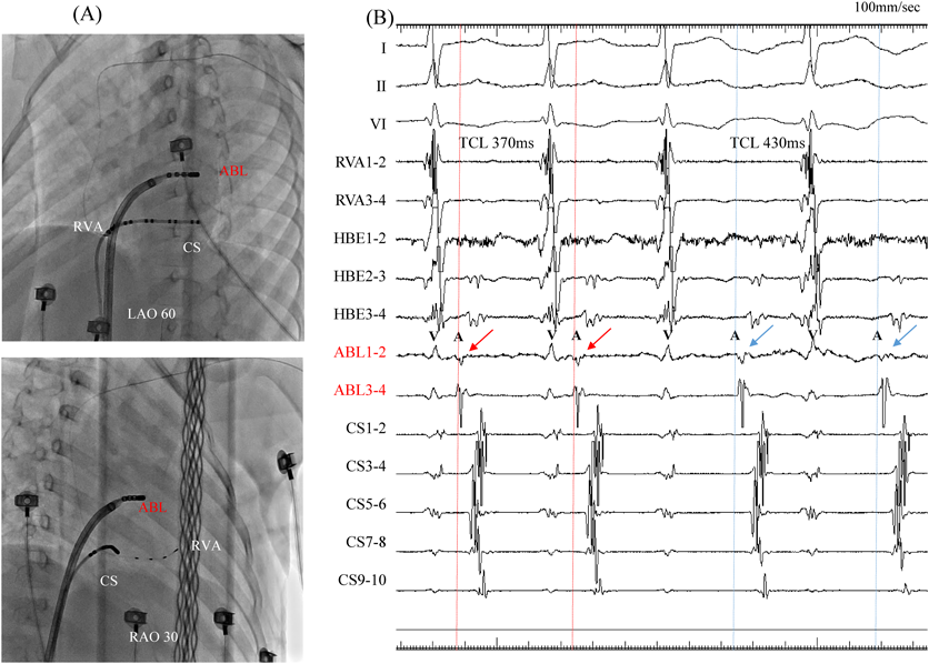
At 5 years and 6 months of age, the patient was referred to our hospital for electrophysiological studies and radiofrequency catheter ablation (RFCA). Her body height was 110 cm and weight 22 kg. We performed these electrophysiological maneuvers under general anesthesia (induced by midazolam bolus injection and maintained by continuous infusion of dexmedetomidine hydrochloride). We inserted a 5Fr sheath into the left basilic vein, and a 5Fr electrode was arranged in the coronary sinus. We then inserted an 8Fr and another 5Fr sheaths into the right femoral vein, and 2Fr electrode catheters (EPstar 2F Multi; Japan Lifeline, Tokyo, Japan) were placed in the high right atrium, the His bundle, and the right ventricular apex. During ventricular pacing, ventriculo-atrial conduction was observed, the earliest atrial activation was at the far distal portion of the coronary sinus (leads CS1 and CS2), and decremental properties were not observed. Narrow QRS complex induced by tachycardic ventricular stimulation intensified in the atrial electrogram as a result of single ventricular stimulation during the His bundle refractory period. A programmed atrial stimulation revealed that the effective refractory period of the antegrade accessory pathway was <600–220 msec. Diagnosed was orthodromic atrioventricular reciprocating tachycardia (AVRT) via the left accessory pathway.
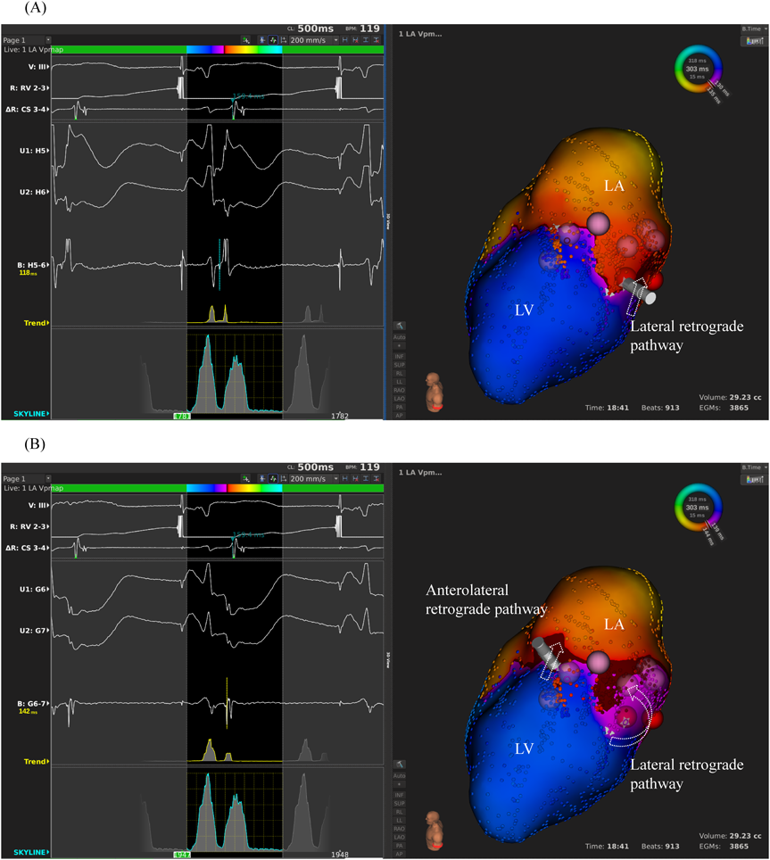
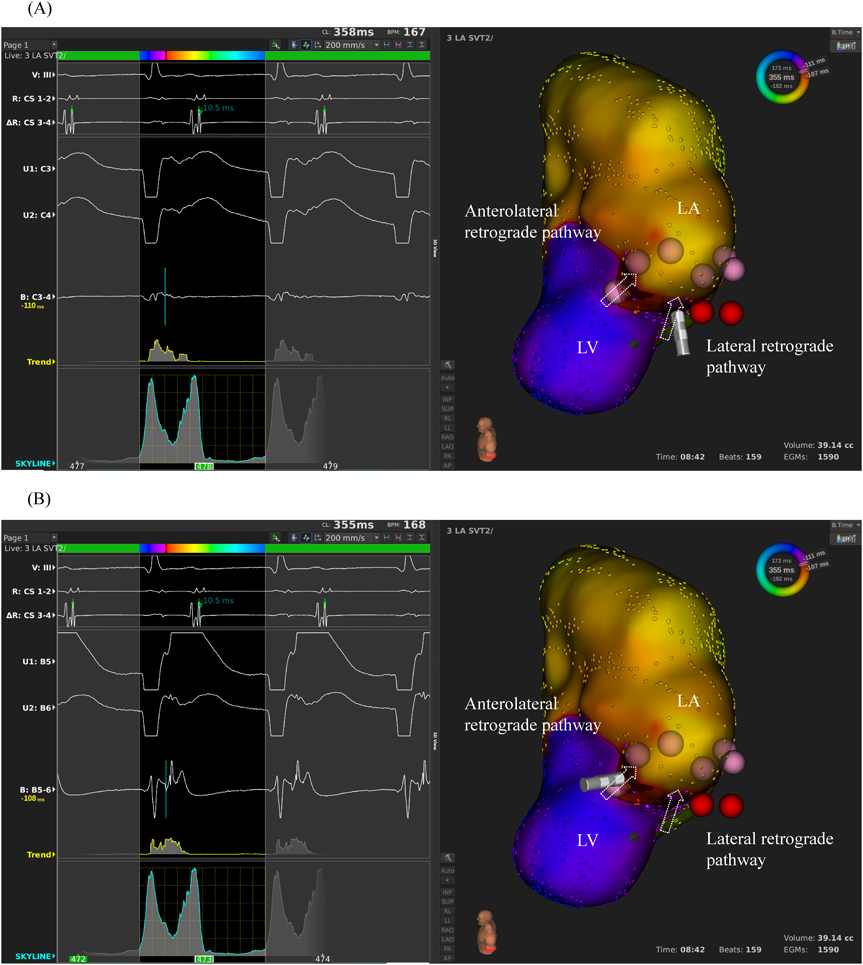
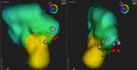
We used intracardiac echocardiography and a radiofrequency needle to perform transseptal puncture, and then inserted a long deflectable sheath (C MAP SYMMETRY; Century Medical, Inc. Tokyo, Japan) into the left atrium. During right ventricular pacing, we used the ORION™ high-density catheter (Boston Scientific) and the RHYTHMIA™ Mapping System to perform activation mapping, which demonstrated early left lateral activation followed by anterolateral atrial activation. Anterolateral activation, however, sometimes occurred as early as left lateral activation (Fig. 2A, 2B). The propagated waves collided at the distal portion of the left atrium through the mitral annulus. On activation mapping, the earliest atrial activation during AVRT coincided with that during right ventricular pacing (Fig. 3A, 3B; Supplementary Movie). Furthermore, 3D mapping showed that these earliest sites of atrial activation were 16.7 mm apart.
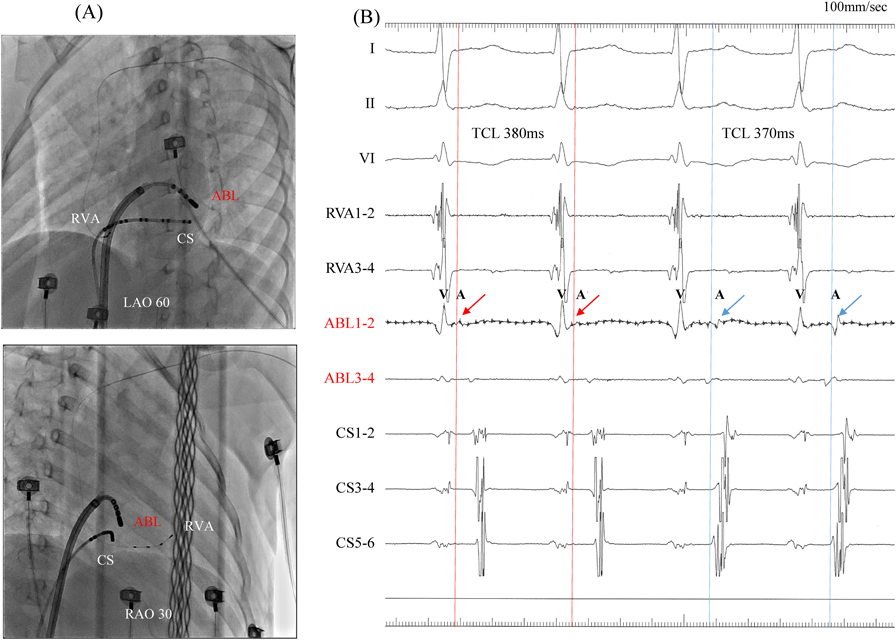
We performed RFCA using a 4-mm tip ablation catheter (Blazer™ II; Boston Scientific Japan, Tokyo, Japan). Firstly, the radiofrequency technique was applied during AVRT to the left lateral site of the atrium, where activation commenced, and conduction through the left lateral accessory pathway was interrupted at 4.3 sec of ablation. Unfortunately, narrow QRS tachycardia persisted, and the earliest atrial activation occurred at the site of the ablation catheter in the left atrium (Fig. 4A, 4B). Atrial electrography showed that the narrow QRS tachycardia still intensified as a result of single ventricular stimulation during the refractory period of the His bundle, indicating AVRT via the left-sided accessory pathway. On repeated activation mapping during AVRT, the earliest atrial activation was at the left anterolateral portion of the mitral annulus. Twelve–lead ECG showed little change in wave morphology after the initial RFCA. Only the P–wave amplitude in lead II increased slightly when the AVRT was reorganized to that via the left anterolateral accessory pathway (Fig. 5). We subsequently performed RFCA on the anterolateral side, terminating the AVRT, and ventriculo-atrial conduction disappeared 5.7 sec after the initiation of ablation (Fig. 6A, 6B). The final diagnosis was for dual AVRTs via separate accessory pathways.
Having eliminated these two accessory pathways, we could still induce a different SVT, which manifested as long RP tachycardia. No ventriculo-atrial conduction occurred with programmed ventricular stimulation; tachycardia was spontaneously induced by atrial stimulation, which led to the diagnosis of focal atrial tachycardia. Activation mapping during focal atrial tachycardia showed that the earliest site of atrial activation was in the left atrial appendage. We performed RFCA on the left atrial appendage, and the focal atrial tachycardia disappeared at 3.9 sec after energy delivery. The electrophysiological studies and RFCA were completed without any complications. Tachycardia has not recurred, even without prescription of antiarrhythmic medications, for the past 24 months.
This study was approved by the Institutional Ethics Committee of Toyama Prefectural Central Hospital (approval number 61-31) and We performed electrophysiological studies and RFCA after receiving written informed consent from her parents.
Using a high-resolution 3D mapping system, we succeeded in confirming two breakthrough activations clearly via the mitral annulus on an activation map in a child with multiple accessory pathways. Ultra–high-resolution mapping is useful for delineating multiple conduction pathways and focal atrial tachycardia. During the first episode of tachycardia in our patient, her SVT was once terminated by the administration of adenosine triphosphate, but it recurred immediately and persisted. This led to the heart condition of tachycardia-induced cardiomyopathy. Such persistent SVT probably consisted of multiple tachycardias, and use of a 3D mapping system may be an important therapeutic strategy for electrophysiological studies and RFCA. The ORION™ catheter was also useful in mapping the left atrial appendage because of its variable shape.
Use of a 3D mapping system enables higher rates of successful ablation in children with Wolff–Parkinson–White syndrome than application of fluoroscopy alone does, because 3D mapping is more accurate in confirming catheter position and location than the classical modality. In the event of an arrhythmic recurrence, the sophisticated system helps the operator navigate more accurately to the site of prior success.2) Recently, Ertuğrul et al. reported that the incidence of multiple accessory pathways was 4.6% among patients who underwent ablation for such accessory pathways, and arrhythmias coexisted in 2.5% of all ablation procedures. Although the rate of successful ablation was 94% among all patients with the Wolff–Parkinson–White syndrome, the figure was slightly lower in patients with multiple accessory pathways (81%).3) It is challenging to ablate all multiple accessory pathways precisely, and thus the ultra–high-resolution 3D mapping system is very useful for locating these pathways and for accurately assessing the propagation of the stimuli.
Accessory pathways are located at the atrioventricular annulus, and understanding of the anatomical orientation of the annulus is important for ablating the accessory pathways. The RHYTHMIA™ Mapping System has intelligent annotation technology marking the largest bipolar potential, which allows physicians to distinguish the atrial from the ventricular potentials simultaneously, and an atrioventricular dual-chamber map can be constructed without manual reannotation. The continuous activation pattern of the accessory pathways from one chamber to another is also useful for understanding the site of the accessory pathways.4) Yanagisawa et al. reported that ultra–high-resolution mapping in adults may facilitate the assessment of multiple conduction pathways simultaneously in a short mapping time, and specific sites can be mapped adequately and quickly.1) We hypothesized that it should be equally useful in small children.
Safety is of concern when the ORION™ mapping catheter and the RHYTHMIA™ Mapping System are used in children. The ORION™ mapping catheter is 8.5Fr in size; therefore, a 9Fr or larger sheath is required for vascular access. According to a previous report, the ORION™ catheter and RHYTHMIA™ Mapping System were safe and accurate for mapping various arrhythmias in pediatric patients whose body weight was >20 kg.5) In addition, the basket of the ORION™ catheter can vary in size, which allows the tip of the catheter to accommodate different cardiac structures. In our 22 kg patient, no adverse events occurred while the RHYTHMIA™ Mapping System was used. Furthermore, detailed geometric characteristics and high-resolution activation mapping were obtained without need of manual reannotation. SVTs with multiple accessory pathways are often found in young patients, and radiation exposure is hazardous especially in this age group. Dual-chamber mapping assisted us to achieve effective ablation with reducing radiation exposure. Mapping the atrium and the ventricle simultaneously was of a help in clarifying the detailed connections of the accessory pathways. Shorter radiation exposure would be advantageous in patients, particularly in children.4) The RHYTHMIA™ Mapping System is accurate and safe to use in the pediatric population.
In conclusion, ultra–high-resolution mapping is safe and useful for delineating multiple accessory pathways in pediatric patients.
 1,Shuhei Fujita1,Akio Chikata2,Kazuo Usuda2,Kiyoshi Hatasaki1Shinichiro Mizutomi